PT2399 Delay Project – The TweakTone Delay
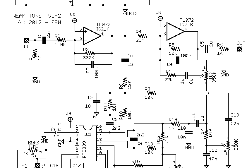
The TweakTone Delay is a PT2399 delay project with highly filtered repeats and the possibility of very long delay times (and minimal delay line noise). There is also a tone control trimmer to adjust the high-pass cutoff frequency on the repeats.
The circuit is based on the Mad Professor Deep Blue Delay, and has been heavily modified to adjust filtering, repeat/echo volume, feedback characteristics, and increased maximum delay time. The added filter control trimmer is also a differentiator, and it could be wired as an external control, if desired.
TweakTone Project Files / Notes
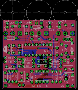
Download the TweakTone PT2399 delay project file pack, which includes: Schematic image, PCB layout image, legacy PCB build guide document with notes, and Eagle CAD files. The layout is for board-mounted pots and fits in a 125B sized enclosure.
The stock values of this PT2399 delay project yield a max delay time of approximately 550ms – 600ms. With a minor modification (see file pack), max delay time can be extended to almost 900ms. Granted, at these longer delay times, the filtering is very aggressive and murky and you will lose some volume from the repeats, which can also change how much feedback there is.
Longer Delay Time
Change the Time pot to A100K and then add a 270K resistor in parallel with Time. You can add the resistor either to the pot pads on the board, or you can use the pads marked “M1” and “M2” (see below for more info on these). Adding the 270K resistor brings the Time pot’s total resistance value down to about 75K, which is about the limit of what this circuit can handle without getting noisy and producing synth-‐like repeats (more resistance = more delay time). If you don’t have 270K on hand, try 220K, but be aware that this will give you less max delay time. Or you could put multiple resistors in series to get close to 270K.
Modulation Add-On
The pads marked “M1” and “M2” are there to make adding off-‐board modulation neater and easier. The original intent was to use an LFO that drives the classic LED/LDR combo to offer variable resistance as the output. However, you do not have to use an optical LFO, and most any LFO designed for PT2399 use will work fine.
Disclaimer: some links on this page are affiliate links.