
How BBDs Work in Analog Delay Pedals
Everybody seems to lust after “analog” pedals of all types, with delay/echo being the most sought after. But what’s going on under the hood of analog delay? The core of any analog delay pedals is the BBD chip, which stands for “bucket brigade device”.
What are BBDs?
BBDs are analog signal processing devices that were widely used in the late 1970s and 1980s for audio effects processing, especially in guitar pedals, synthesizers, and recording equipment. They operate on the principle of moving a signal sample by sample from one stage to another in a series of analog capacitors. This allows for the creation of a time delay and the addition of feedback loops to create echo, delay, chorus, and flanging effects.
The basic building block of a BBD is a “stage” made from a capacitor and switching transistor, each of which is connected to a charge injector and a charge detector. The charge injector puts an electrical charge into the capacitor, and the charge detector measures the amount of charge stored in the capacitor.
Why is it Called “Bucket Brigade”?
Back before modern firefighting equipment, firefighters would sometimes for a bucket brigade to get water from its source to a fire. The men would stand in a long line, each man holding a bucket, and pass water from one bucket to another all the way down the line. A BBD chip does something sort of similar: it passes a signal from one “bucket” to another from the chip’s input to its output. Only instead of buckets, a BBD has an array of capacitors that hold and then pass the signal. The more capacitors (buckets) there are, the longer it takes for the signal to go from input to output. And that’s how the delay in signal is created.
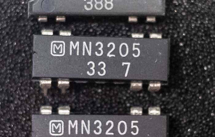
The amount of capacitor buckets in a BBD is, generally speaking, expressed as a number of “stages”. The more stages there are, the more delay time is possible. For example, the sought-after MN3005 BBD (popular with delays, like the Boss DM-2) has 4,096 stages, which equals around 300 milliseconds of delay time at maximum. By comparison, the MN3207 (often used for a chorus effect) has 1,024 and is capable of up to around 50 ms of delay time.
How BBDs Work
To understand how BBDs work, it is helpful to first understand how a basic delay circuit works. A delay circuit takes an input signal and delays it by a certain amount of time before outputting it. The most basic way to create a delay circuit is to use a simple RC (resistor-capacitor) circuit, which consists of a capacitor and a resistor in series. When an input signal is applied to the circuit, the capacitor charges up to the level of the input signal through the resistor. When the input signal is removed, the capacitor discharges through the same resistor, causing a time delay before the output signal drops to zero.
BBDs use a similar principle, but instead of a single capacitor and resistor, they use a chain of capacitors connected in series. The input signal is injected into the first capacitor in the chain, and then the charge from that capacitor is transferred to the next capacitor in the chain. This transfer of charge is accomplished by controlling the voltage on a series of switches that connect each capacitor to the next in sequence.
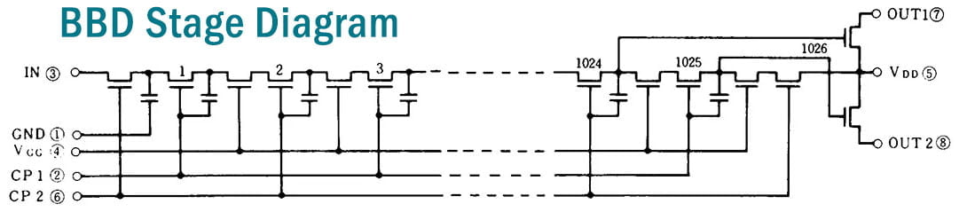
Here’s an abbreviated diagram of how the stages are set up inside a BBD integrated circuit package. This one shows a 1,024-stage BBD, such as an MN3007 or MN3207.
BBD Oscillator Circuit
The charge transfer process is controlled by a clock signal, which causes the switches to open and close at a precise rate. The clock signal is generated by an oscillator circuit that typically operates at a frequency in the range of a few hundred kilohertz to a few megahertz. The clock signal determines the delay time of the BBD, as each capacitor in the chain represents a fixed delay time. Typically, the oscillator circuit is built around a purpose-made companion chip that simplifies the implementation, such as MN3101 and MN3102, although other options are available. The Electro-Harmonix Deluxe Memory Man, for example, utilizes a CD4047 (which is a monostable/astable multivibrator).
That Classic BBD “Warm” Sound
All this technical stuff is great, but what does it really mean in terms of the only thing guitarists care about: tone?
BBDs introduce noise and distortion to the original input signal. Between some signal from the oscillator clock circuit bleeding into the audio (often referred to as “clock noise”) and also the aliasing noise generated by the reconstructed audio from the output of the BBD, the raw audio coming out of a BBD sounds pretty bad. There are ticks from the oscillator, as well as a metallic-sounding overtone that a lot of people describe as “clang”. The longer the delay time the BBD is set for, the more noise is introduced.
To overcome these unmusical noise types, two main tools are utilized: 1) a compressor / expander sub-circuit, and 2) active and passive filtering (covered below). The result of all this filtering and compression is a dark, warm, subjectively “smooth” sound to the delay repeats, which many guitarists like. Because there is a fair bit of low-pass filtering, the repeats are always darker than the input signal and tend to “melt into the background” in a way that is pleasing to the ear.
Compander
The compander integrated circuit is required for BBD-based delay circuits. The name comes from a combination of its two functions: compressor and expander. The part numbers most common are NE570, NE571, SA571. Similar to a dual op amp such as the popular TL072, a compander has two identical compressor/expander circuits in one package. Either can be configured as a compressor or expander based on the circuit configuration. In a BBD-based delay, one half of the compander is configured as a compressor, and the other half is set up as an expander. Companders were developed to help reduce noise and data size for “land line” telecommunications.
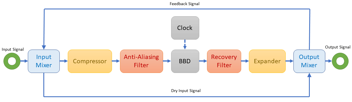
To minimize overall noise, the input signal is compressed by the first half of the compander, and is then sent to an active low-pass filter, and then is fed to the BBD. The output from the BBD is then directed to another active low-pass filter and is then fed back to the other half of the compander, which is set up as an expander. Compressing the signal before the BBD helps reduce input noise while also limiting the signal amplitude to below the max headroom of the BBD (prevents clipping). Expanding the signal after the BBD brings it back up to a similar volume as the raw input.
That’s a lot of words, but here is a process flow diagram that makes it a bit easier to digest:
Filtering
As shown in the process flow diagram above, there are two discreet filter sections of any given BBD-based circuit. The first is known as an anti-aliasing filter, which reduces the highest frequencies of the audio signal. BBDs don’t handle high frequencies very well, so this filter helps get the signal to a frequency range best suited for BBDs to do their thing.
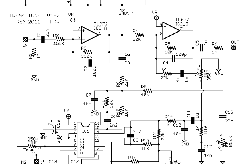
Here’s an example anti-aliasing filter pulled from the AquaBoy Deluxe schematic by madbean pedals:
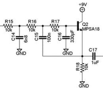
Once the signal has passed through all the stages in the BBD, it proceeds to another low-pass filter that reduces clock noise (often described as a whine) and also shaves off some high-end hiss introduced by the BBD. The second filter is configured very similarly to the anti-aliasing filter (called a Sallen-Key topology) but with a different (steeper) cutoff frequency usually accomplished with two complete filters in series.
The use of companding and two stages of active low-pass filtering team up to deliver that iconic soft, warm, dark echo sound that makes analog delays sound the way they do.