Effects Projects

CMOS Eisley – CD4049 Tremolo – Schematic

After much delay (but no echo), I present a meager contribution to the world of DIY effects pedals: the CMOS Eisley CD4049 Tremolo. It uses a single CD4049 IC for both audio path and low frequency oscillator (LFO), yet remains tick-free (a frequent problem when sharing audio and LFO on a single chip). It’s got Speed, Depth, and Volume controls, and uses 5 of the 6 inverter gates in the CD4049. The schematic shows a vactrol, but you can use an LDR + LED in a discreet setup and it should work just fine (as long as the LDR can get to around 1M max dark resistance).

CMOS Eisley

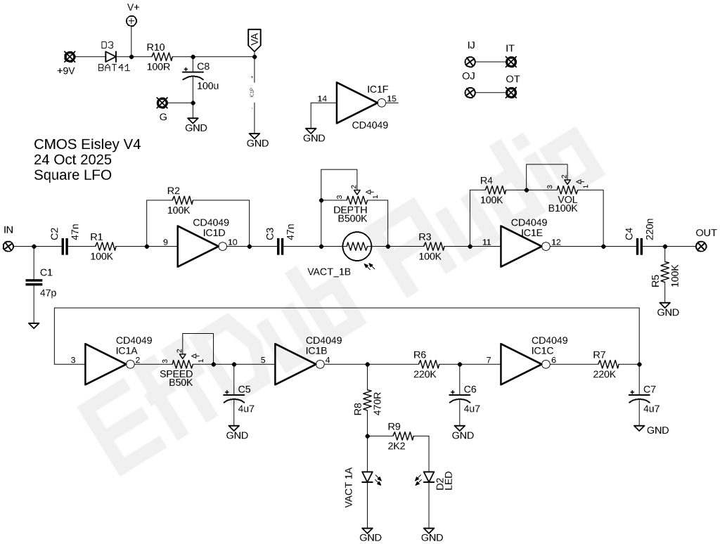
This version is square-wave only. I tried several options for also offering triangle wave option, but couldn’t get them both to place nice in one LFO. If you want a smoother (but never really totally smooth) waveform, add a very large cap (at least 2200uF) between the junction or R8 / R9 and ground. This will impact the overall speed range of the LFO, so you’ll also need to somewhat adjust some of the other passives to get speeds that are all in a usable range again.

The spare inverter could probably be used to buffer the vactrol’s LED. It doesn’t really need it, but it would be an interesting exercise to add it, and would likely make the triangle wave option more stable.

The idea came from stumbling on to an old article about using CMOS inverters to build oscillators. And since I had long known they could also be used for audio amplification, I figured maybe a tremolo would work. And it does, much to my surprise.

Frankly, this is far more of a “hey, I wonder if this will work” than it is a truly useful circuit. There are better tremolos out there with only slightly higher part counts (such as the Shoot the Moon, by yours truly). But, it does it’s job well as a square-wave tremolo, and as far as I know there’s nothing out there quite like it in terms of circuit topology. Give it a go on breadboard and see for yourself. It’s not too bad as a breadboard build.

DIY Effects Info

Making PCBs with a Fiber Laser (video)

I recently picked up a 20W fiber laser machine and immediately set about figuring out how to use it for pedal making purposes. Obviously it’s great for etching powdercoat off of enclosures, but it can also engrave into metal. And I also discovered that it can etch, “drill”, and cut out PCB from copper clad blanks. I’m still working out the final details for speeds, power, and frequency, but I’m getting very close. When it’s all done, I will publish the settings so others can use with their machines.

It’s also possible to do double-sided boards, but the process is a bit more complicated as you need to sort out some kind of very accurate alignment jig setup. So for now, just single-sided boards. Read More

Effects ProjectsPedals for Sale

Basic Metal: A FET-tastic dirt circuit

After much tweaking and some setbacks, I’m pleased to announce that my take on the classic “hard-rock / vintage metal” sound is, at long last, ready for public consumption. This one is 100% “discrete” in the sense that there are no integrated circuit components (operation amplifiers or other ICs). It’s all field-effect transistors doing the amplifying and clipping…there aren’t even any clipping diodes in this circuit. There ARE diodes in the circuit, but they are for polarity and over-voltage protection (not in the audio path). Read More

DIY Effects InfoEffects Projects

Charge Pump from CMOS Inverter gates? Yes!

About 12 years ago (yikes!), I came across a rather interesting concept: it’s possible to use CMOS inverters to step up input voltage much the same way as dedicated charge pump ICs work. I loved this idea because it would be cheaper (much cheaper) to play with higher supply voltages for pedal circuits while keeping with the standard single-supply +9V input voltages that have ruled the pedal world from the beginning. Read More

Effects Projects

Dead Easy Dirt V2 – Reboot of my old design

Back in 2012, I put together the simplest circuit I could think of, which was a couple caps, a resistor or two, some diodes, and an LM386 amplifier IC. I left out everything that was 100% necessary for a functional circuit, including polarity protection, pulldown resistor, and power filtering. Lots of people built that simple circuit, so I thought I would update it a bit to include a few basic improvements that I had omitted from the original. The design owes a lot to the Big Daddy from RunoffGroove. Read More

Pedals for Sale

Actually, it’s a different tremolo coming first: CMOS Eisley

Just got these boards in today and have begun the first prototype build. It’s an optical tremolo with both the audio path and LFO made from a single CD4049 CMOS hex inverter. Despite having it all function in a single IC, there is no LFO ticking in the audio. Two of the inverters are the audio path (input and output amplifiers), and three more inverters are arranged as a low-frequency oscillator. And the last inverter is unused (I may do another iteration later that uses this last inverter to add a bit of grit/drive). Read More

Pedals for Sale

Coming Soon: Tap Temp Optical Tremolo

I’m pleased to announce the first of a few pedals that will be hand built by me in small batches and sold as cheaply as I can manage. There are cheap Chinese pedals galore these days, but I want to try and get as close to I can to slave-labor prices but made in the USA. Think of it as “shabby chic” or maybe “bespoke” rather than old-school “boutique.”

Read More

Effects Projects

The Wahscillator – An LFO-driven Filter

I always liked the original ROG Phozer’s base sound, but the LFO wasn’t really that useful at lower speeds. So I took the basic idea, which is the Tim Escobedo’s Idiot Wah + LFO, and kicked it up a notch. Instead of the Phozer’s input JFET buffer, I went with an op amp buffer, and since there’s an extra amp in the package, I also added an output buffer. The LFO is the Shoot The Moon tremolo. For the variable resistor element, just about any of the usual suspects will work: LED/LDR combo, vactrol, or even one of those optical ICs such as the H11F1. And that’s how the Wahscillator came to be. Read More

Effects Projects

The Snitch: a ProCo Rat clone project

There are many Rat clone projects out there, but this one is mine. This is a part-for-part clone of the original Rat circuit. There are no extra pots or switches…just three knobs of ass-kicking tone in a small PCB form factor. It’s laid out for 1N4148 / 1N914 diodes, but you could use pretty much whatever you want to mimic the various Rat version. My suggestions:

  • 1N4148 / 1N914 – Classic Rat
  • LEDs (diffused) – Turbo Rat
  • BAT41 or similar Schottky diode – You Dirty Rat (please don’t waste a real Germanium diode on a YDR build)
  • 1x 1N914 + 1x LED – Overpriced boutique Rat variant with an unnecessarily self-aggrandizing name

Read More

Verified by MonsterInsights