Author: effdub

Effects ProjectsPedals for Sale

Basic Metal: A FET-tastic dirt circuit

After much tweaking and some setbacks, I’m pleased to announce that my take on the classic “hard-rock / vintage metal” sound is, at long last, ready for public consumption. This one is 100% “discrete” in the sense that there are no integrated circuit components (operation amplifiers or other ICs). It’s all field-effect transistors doing the amplifying and clipping…there aren’t even any clipping diodes in this circuit. There ARE diodes in the circuit, but they are for polarity and over-voltage protection (not in the audio path).

What does it sound like?

To me, it sounds sort of like a pushed Marshall JCM800 or an Orange Rockverb cranked up. With the GAIN set high, it’s got boatloads of compression and sustain and also a lightly fuzzy low end (but still fairly tight). At lower gain settings, the bass cleans up. It does NOT sound like the classic Mesa high-gain tone.

Bands I think it sounds appropriate for: Black Sabbath, AC/DC (lower gain settings), Guns n’ Roses, Ghost, Faith No More, Iron Maiden, Van Halen, Ratt, Poison, and a bunch of other hair metal bands. This very subject, of course.

Circuit Details – Basic Metal

The Basic Metal is a total of five cascaded / series gain stages: a single JFET input amplifier (boost) driving four MosFET amplifiers, followed by a simple variable low-pass filter tone control. The GAIN control sits between the JFET boost and the rest of the circuit. There is also a high/low gain switch that toggles a bypass capacitor on the JFET’s source pin. The TONE control is taken directly from the venerable ProCo Rat (why mess with simplistic perfection?).

Additionally, there is an output gain trimmer that sets the gain of the final MosFET amplifier. This is to fine-tune the max gain available and allow for compromise between gain and noise. And finally, there is a bias trimmer to dial in the JFET and a bias pad to easily read the voltage with a multimeter.

Availability

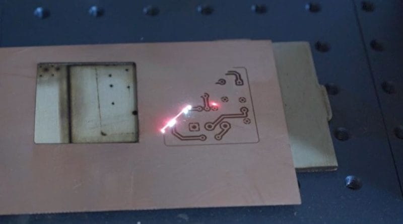
I will be building some fully finished pedals using the Basic Metal circuit, with laser-etched wood faceplates. I will also be making the boards available so folks can build their own. I will post an update when things are progressing. Final boards have just been ordered, so it shouldn’t be long.


DIY Effects InfoEffects Projects

Charge Pump from CMOS Inverter gates? Yes!

About 12 years ago (yikes!), I came across a rather interesting concept: it’s possible to use CMOS inverters to step up input voltage much the same way as dedicated charge pump ICs work. I loved this idea because it would be cheaper (much cheaper) to play with higher supply voltages for pedal circuits while keeping with the standard single-supply +9V input voltages that have ruled the pedal world from the beginning. Read More

Effects Projects

Dead Easy Dirt V2 – Reboot of my old design

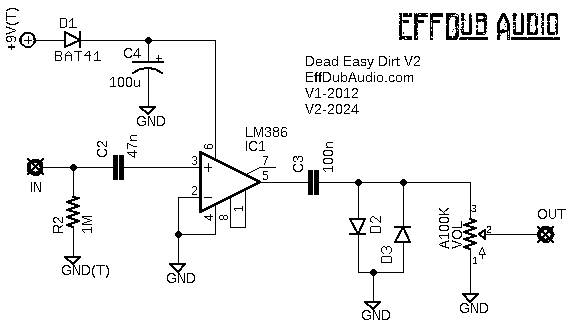
Back in 2012, I put together the simplest circuit I could think of, which was a couple caps, a resistor or two, some diodes, and an LM386 amplifier IC. I left out everything that was 100% necessary for a functional circuit, including polarity protection, pulldown resistor, and power filtering. Lots of people built that simple circuit, so I thought I would update it a bit to include a few basic improvements that I had omitted from the original. The design owes a lot to the Big Daddy from RunoffGroove.

This one is perfect for breadboarding and experimenting. Try different diode types for D2 / D3, add a gain control via a pot between pins 1 and 8, change up the input and output caps, throw a simple boost in front, etc.

Also works great for building on perf or vero/strip board.

Dead Easy Dirt

Disclaimer: some links in this post may be affiliate links.

Pedals for Sale

Actually, it’s a different tremolo coming first: CMOS Eisley

Just got these boards in today and have begun the first prototype build. It’s an optical tremolo with both the audio path and LFO made from a single CD4049 CMOS hex inverter. Despite having it all function in a single IC, there is no LFO ticking in the audio. Two of the inverters are the audio path (input and output amplifiers), and three more inverters are arranged as a low-frequency oscillator. And the last inverter is unused (I may do another iteration later that uses this last inverter to add a bit of grit/drive).

There are three controls: Speed (pot), Depth (pot), and Triangle/Square (switch). The switch controls the wave shape of the LFO. Be default, the LFO products a VERY square output. To try to smooth this out as much as possible, I added a very large capacitor as a rudimentary low-pass filter on the wave. The result is pretty close to a triangle wave shape. And the switch allows you to choose which wave shape you want to use (obviously). There is also an LED to indicate LFO speed, and it is lit even when the pedal is bypassed. The pedal will be available with either a standard 3PDT mechanical bypass switch or with a relay-driven soft-touch bypass switch (modest upcharge for the latter).

I hope to have a demo video posted soon, and after that I plan to sell these primarily through a local music shop (who will ship pretty much anywhere), but I will also sell direct if someone would prefer that.

Pic of the mostly populated board:

cmos eisley


Pedals for Sale

Coming Soon: Tap Temp Optical Tremolo

I’m pleased to announce the first of a few pedals that will be hand built by me in small batches and sold as cheaply as I can manage. There are cheap Chinese pedals galore these days, but I want to try and get as close to I can to slave-labor prices but made in the USA. Think of it as “shabby chic” or maybe “bespoke” rather than old-school “boutique.”

Read More

Effects Projects

The Wahscillator – An LFO-driven Filter

I always liked the original ROG Phozer’s base sound, but the LFO wasn’t really that useful at lower speeds. So I took the basic idea, which is the Tim Escobedo’s Idiot Wah + LFO, and kicked it up a notch. Instead of the Phozer’s input JFET buffer, I went with an op amp buffer, and since there’s an extra amp in the package, I also added an output buffer. The LFO is the Shoot The Moon tremolo. For the variable resistor element, just about any of the usual suspects will work: LED/LDR combo, vactrol, or even one of those optical ICs such as the H11F1. And that’s how the Wahscillator came to be. Read More

Effects Projects

The Snitch: a ProCo Rat clone project

There are many Rat clone projects out there, but this one is mine. This is a part-for-part clone of the original Rat circuit. There are no extra pots or switches…just three knobs of ass-kicking tone in a small PCB form factor. It’s laid out for 1N4148 / 1N914 diodes, but you could use pretty much whatever you want to mimic the various Rat version. My suggestions:

  • 1N4148 / 1N914 – Classic Rat
  • LEDs (diffused) – Turbo Rat
  • BAT41 or similar Schottky diode – You Dirty Rat (please don’t waste a real Germanium diode on a YDR build)
  • 1x 1N914 + 1x LED – Overpriced boutique Rat variant with an unnecessarily self-aggrandizing name

Read More

DIY Effects Info

Tim Escobedo “Circuit Snippets” from FolkUrban.com

I have spent countless hours pouring over the circuits and notes that used to be hosted on a strange little website called Folk Urban (used to folkurban.com but it’s gone now). These so-called “circuit snippets” from a guy named Tim Escobedo (RIP) has inspired so many DIY pedal hobbyists to build pedals, create new circuits, and learn about electronics. Tim’s impact on the DIY pedal scene cannot be overestimated. His amazing insights and creative ideas will be sorely missed. Read More

Verified by MonsterInsights