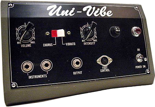
Is the Univibe a Phaser?
There have been many an online (and offline) argument about the nature of the classic Univibe pedal. Is the Univibe a phaser? Is it a vibrato? Or is it something in between or something altogether different? Read More

There have been many an online (and offline) argument about the nature of the classic Univibe pedal. Is the Univibe a phaser? Is it a vibrato? Or is it something in between or something altogether different? Read More
I have spent countless hours pouring over the circuits and notes that used to be hosted on a strange little website called Folk Urban (used to folkurban.com but it’s gone now). These so-called “circuit snippets” from a guy named Tim Escobedo (RIP) has inspired so many DIY pedal hobbyists to build pedals, create new circuits, and learn about electronics. Tim’s impact on the DIY pedal scene cannot be overestimated. His amazing insights and creative ideas will be sorely missed. Read More
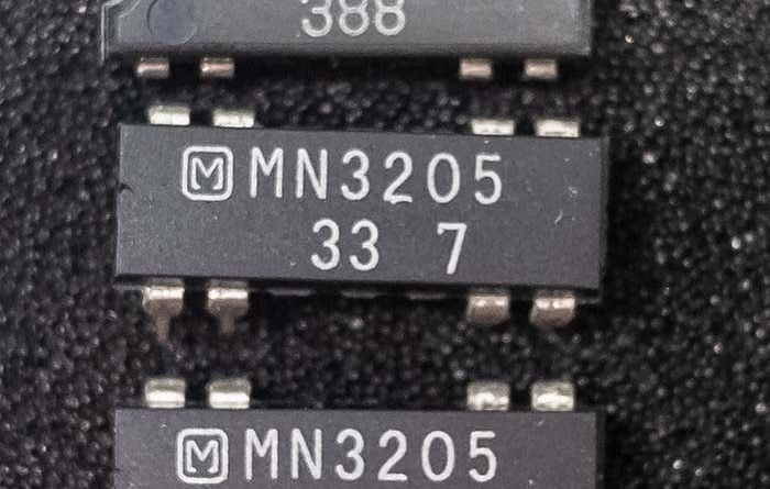
Everybody seems to lust after “analog” pedals of all types, with delay/echo being the most sought after. But what’s going on under the hood of analog delay? The core of any analog delay pedals is the BBD chip, which stands for “bucket brigade device”. Read More
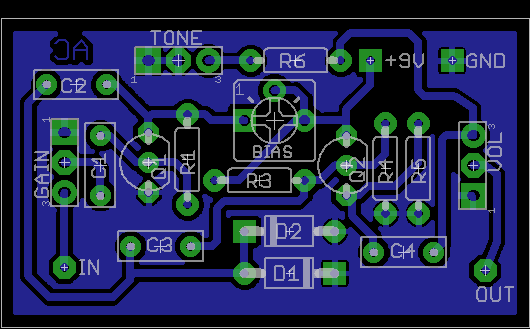
Thought I’d redraw the classic Astrotone circuit and tinker around a bit. With some mods, it sort of reminds me of a light-weight version of the Colorsound Overdriver. The schematic in the File Pack below has the vintage parts values (to the best of my knowledge). I’m calling this the AstroClone since it’s an Astrotone Fuzz clone (duh).
Included in the AstroClone File Pack is artwork for etching (600 DPI), schematic and layout images, and Eagle CAD files.
And below is the BOM for my take on the circuit. I dropped the tone control because it’s useless. I also changed up things a bit to get a little more output and a little more grit.
R1 – 2M2
R2 – 33K
R3 – 1M
R4 – 470K
R5 – 2K2
R6 – omit
C1 – 1µ
C2 – 47n
C3 – 47n
C4 – 47n
D1 – BAT41 (any schottky will work)
D2 – 1N914 (any silicon will work)
Q1 – 2N4401
Q2 – 2N5089
GAIN – B250K
VOL – A25K
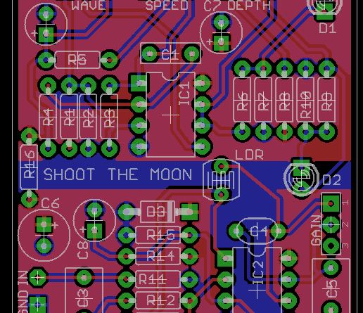
The Shoot the Moon Tremolo is an optical tremolo originally based on the excellent Tremulus Lune circuit by 4MS/CommonSound. The audio path is similar, but the LFO has been simplified to three controls: Speed, Depth, and Shape (wave shape). The power supply section has also been overhauled to provide better electrical isolation between the LFO and the audio portions of the circuit, and both sections are physically isolated as well. The result is a dead-quiet tremolo that goes from triangle wave to almost square wave (that is, smooth to choppy).
There is also a Gain control so that the output of the circuit can be set for unity gain; or it could be used as a boosted tremolo, if desired. Additionally, with the Depth at minimum and Boost set to greater than unity gain, the circuit can be used as a handy-dandy op amp booster with no amplitude modulation at all.
Download the Shoot the Moon Tremolo file pack.
Contains: Schematic image, PCB layout image, legacy PCB build guide document with notes, and Eagle CAD files.
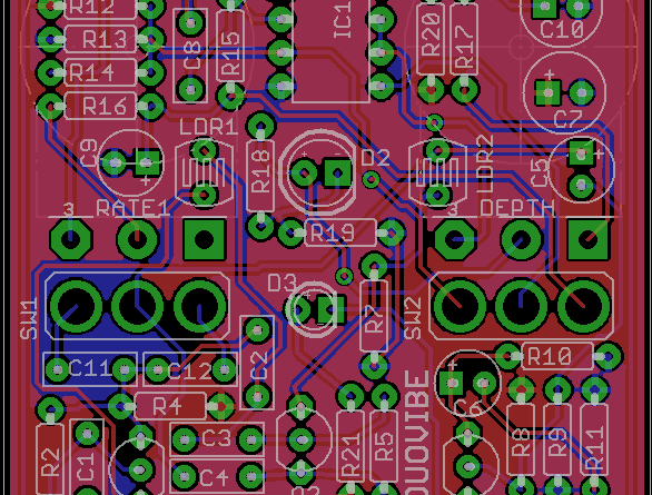
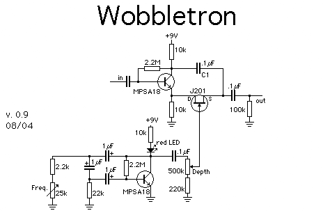
The DuoVibe is an optical vibe / phaser and is yet another expansion on Tim Escobedo’s “Wobbletron” circuit snippet first published in 2005 (which is also very similar to the basic phase shift stages in the classic Univibe circuit). I have done several iterations on this cool little building block snippet over the years, and I feel that this one is a nice compromise between simplicity and functionality.
The DuoVibe is a two-stage optical vibe circuit than can also cop subtle phaser tones. The LFO is modified from the Shoot the Moon Tremolo (itself derivative of the Tremulus Lune) and is capable of triangle wave and near-square wave output. The pitch bend in vibe mode is discernible but not capable of “seasick” wobble. With the depth cranked, you can think of it as a sort of “tremolo with pitch funk going on” kind of thing.
There is a Vibe/Phase Mode switch, the name of which indicates its function and purpose. This switch simply toggles a feedback filtering cap value, but is useful despite the simplicity. See the mods section in the downloadable file pack below.
Download the DuoVibe file pack.
Contains: Schematic image, PCB layout image, legacy PCB build guide document with notes, and Eagle CAD files.
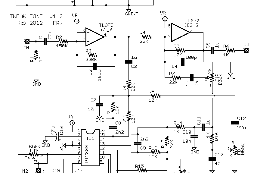
The TweakTone Delay is a PT2399 delay project with highly filtered repeats and the possibility of very long delay times (and minimal delay line noise). There is also a tone control trimmer to adjust the high-pass cutoff frequency on the repeats.
The circuit is based on the Mad Professor Deep Blue Delay, and has been heavily modified to adjust filtering, repeat/echo volume, feedback characteristics, and increased maximum delay time. The added filter control trimmer is also a differentiator, and it could be wired as an external control, if desired.
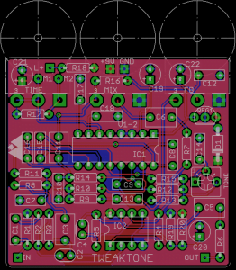
Download the TweakTone PT2399 delay project file pack, which includes: Schematic image, PCB layout image, legacy PCB build guide document with notes, and Eagle CAD files. The layout is for board-mounted pots and fits in a 125B sized enclosure.
The stock values of this PT2399 delay project yield a max delay time of approximately 550ms – 600ms. With a minor modification (see file pack), max delay time can be extended to almost 900ms. Granted, at these longer delay times, the filtering is very aggressive and murky and you will lose some volume from the repeats, which can also change how much feedback there is.
Change the Time pot to A100K and then add a 270K resistor in parallel with Time. You can add the resistor either to the pot pads on the board, or you can use the pads marked “M1” and “M2” (see below for more info on these). Adding the 270K resistor brings the Time pot’s total resistance value down to about 75K, which is about the limit of what this circuit can handle without getting noisy and producing synth-‐like repeats (more resistance = more delay time). If you don’t have 270K on hand, try 220K, but be aware that this will give you less max delay time. Or you could put multiple resistors in series to get close to 270K.
The pads marked “M1” and “M2” are there to make adding off-‐board modulation neater and easier. The original intent was to use an LFO that drives the classic LED/LDR combo to offer variable resistance as the output. However, you do not have to use an optical LFO, and most any LFO designed for PT2399 use will work fine.
Disclaimer: some links on this page are affiliate links.
Back in the day, the Zen Drive from Hermida Audio was a super-hot, super-hyped, super-loved boutique overdrive pedal. It was on everyone’s board, from P&W church bands to post-rock hippie ensembles. Many said it was magical and unlike any other drive pedal; some said it was “just a Tubescreamer with big price tag”. Turns out they were both wrong. It’s actually a semi-original drive circuit, starting off like a Tubescreamer but ditching the famous “mid-hump” tone control and opting instead for a simpler buffered passive tone (high) cut, as well as adding the “Voice” control that adjusts frequency gain in the first op amp stage. Cool, I suppose. If you’re into that kind of thing.
So I figured I’d rustle up my own Zen Drive PCB layout. I made this one way back in the days when doing so would get you branded as a “pirate” or “thief” or even “terrorist.” Hyperbole is a crutch for the callow and unimaginative carnival barkers of society. 🙂
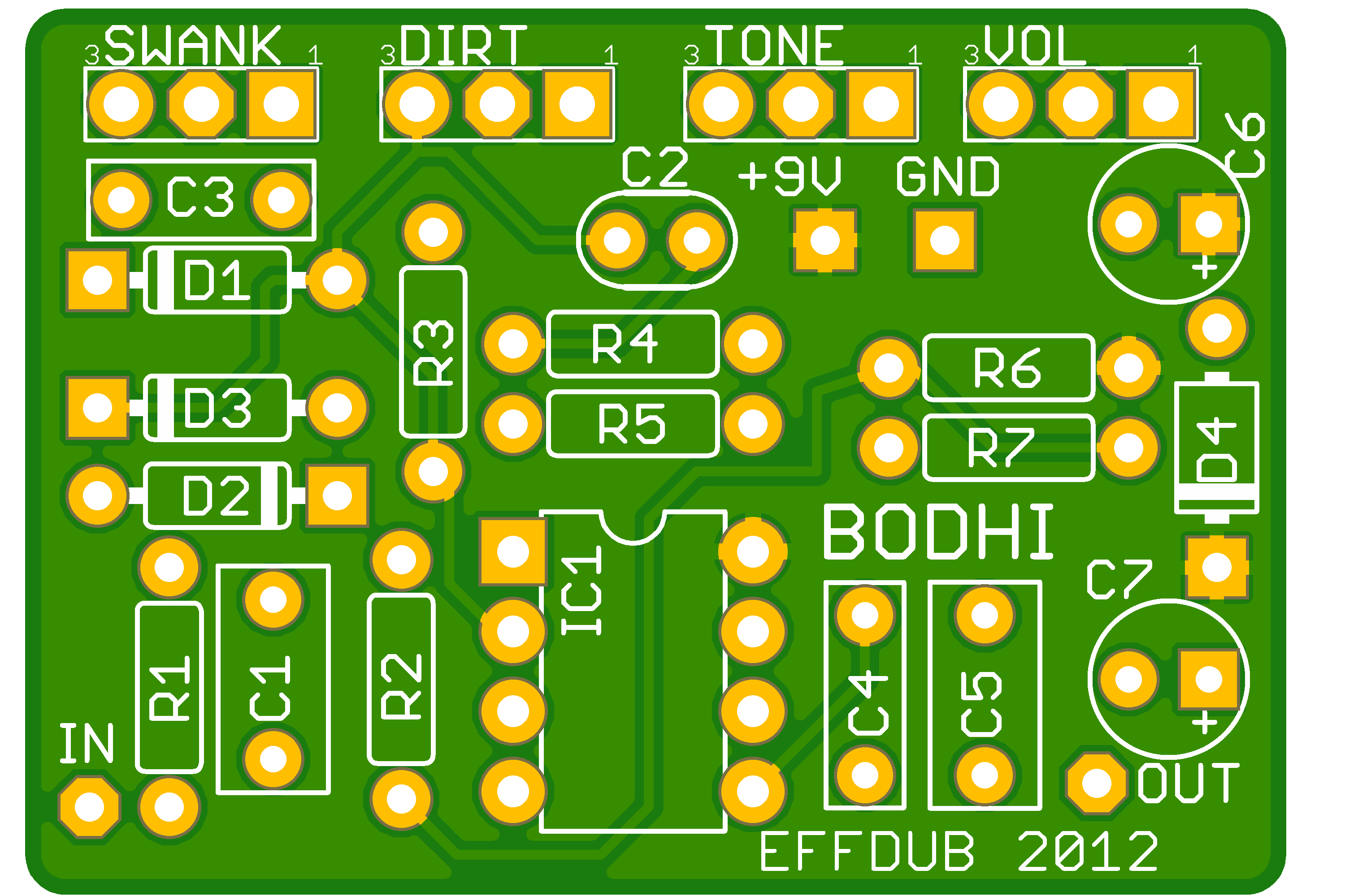
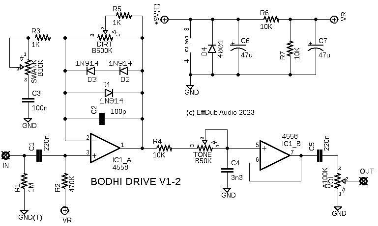
This layout has offboard wiring of everything, which makes it suitable for the DIY who doesn’t want to be constrained by precise drill layouts. I updated the artwork in 2023, but the original layout dates from 2012.
Download the Bodhi File Pack, which includes Eagle CAD files, schematic and PCB images, and gerber files for having your own PCBs fabricated.
The Onesie project is my contribution (one of them, anyway) to the long and glorious history of a fantastic DIY fuzz circuit known as the Bazz Fuss. It’s super simple and sounds fantastic. With just one transistor, one diode, two capacitors, one resistor, and one potentiometer, the Bazz Fuss delivers a hell of a lot of fuzzy goodness despite it’s simplistic design. It’s very difficult to get great tone out of such a small number of components, with the only other similarly efficient circuit I can think of being the Electra Distortion.
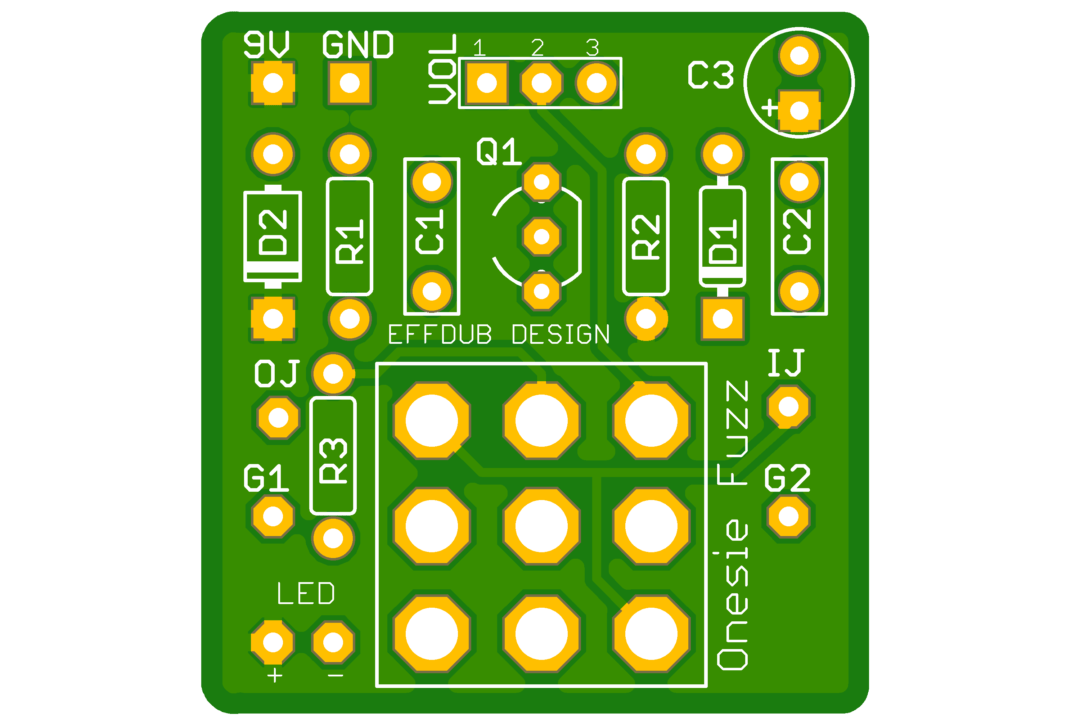
This iteration of the Bazz Fuss stays true to the original (brought to you by a fellow known as “Hemmo” and popularized by the fine folks at RunoffGroove.com), but is built on a PCB that mounts directly to a 3PDT footswitch. This avoids the necessity of precise enclosure drilling, as you can mount the pot anywhere you like and simply run leads from the switch-mounted PCB.
The layout includes pads for bypass LED and current-limiting resistor, as well as power filtering and reverse power polarity protection. It’s very easy to build, and very cheap to have PCB fabricated. It’s a DIY dream, in other words.
Download the Onesie File Pack, which includes schematic and PCB images, Eagle CAD files, and a bonus turret or eyelet layout image.
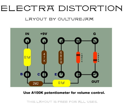
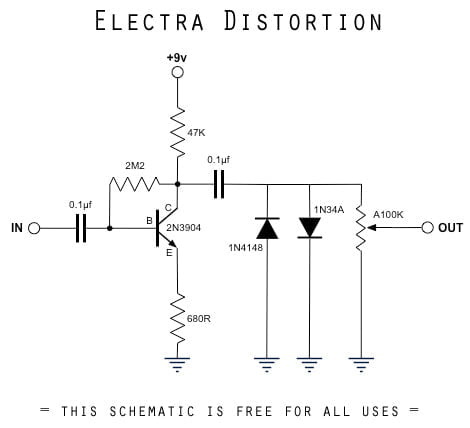
Several people have asked me to repost my older layouts for the often copied (and frequently sold for big bucks, see below for details) Electra Distortion circuit. This is a surprisingly good-sounding circuit for so few components. No fancy parts needed; just a fun little circuit that swings way above its weight.
The name is a little misleading, though. It’s really not a distortion in the modern sense of the word. At best, it’s a medium overdrive gain-wise.
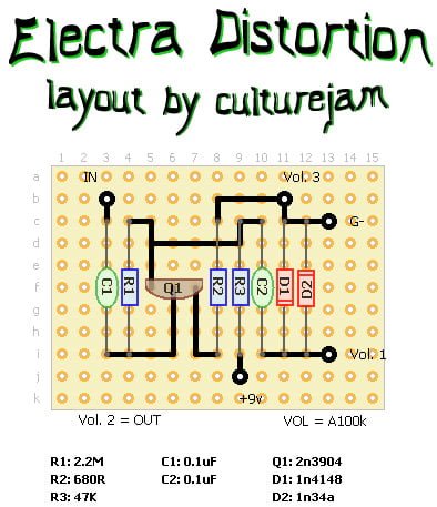
My old schematic drawing and two different DIY layouts for the Electra Distortion are posted below. One is for perf board and the other is for building the Electra on an eyelet, turret, or strip board.
If you like simplicity and great tone, also check out my “Onsie”, which is a very classic take on the old Bazz Fuss circuit, as well as my “SmallBazz” project, which is a germanium mojo-infused version of the Bazz Fuss.
The first one is for perfboard, while the second is for an eyelet / turret style build.
As mentioned above, the Electra has made its rounds in the boutique pedal world, ranging back to the earlier days when everything was a mystery and before folks like FreeStompBoxes were willing to tear things apart and see what was under the hood. Perhaps the best known, and widest selling, is/was the Church of Tone 50 by Lovepedal. Also knowns as “COT50”, there were no less than a dozen different slight variations of this pedals sold over many years, all being slight mods on the classic Electra original.
Lovepedal also sold other pedals with essentially the same circuit (very minor changes), including: Les Lius, Tchula, Champ, JTM, and others. The mileage squeezed out of this one simple circuit is simply astounding.
Another very successful Electra variant is the Speaker Cranker from Earthquaker Devices.
Disclaimer: some of the links on this page are affiliate links.